Wireless DMX,
no compromises.

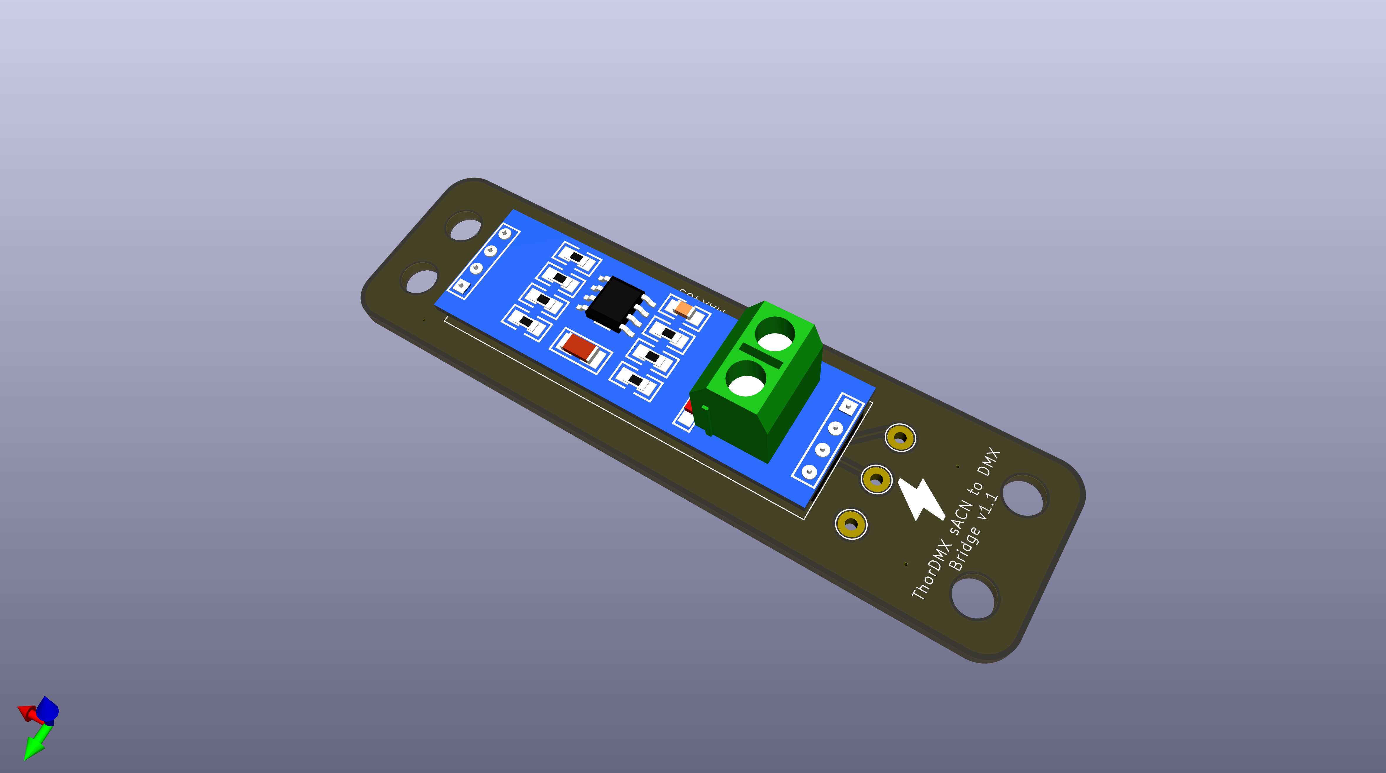
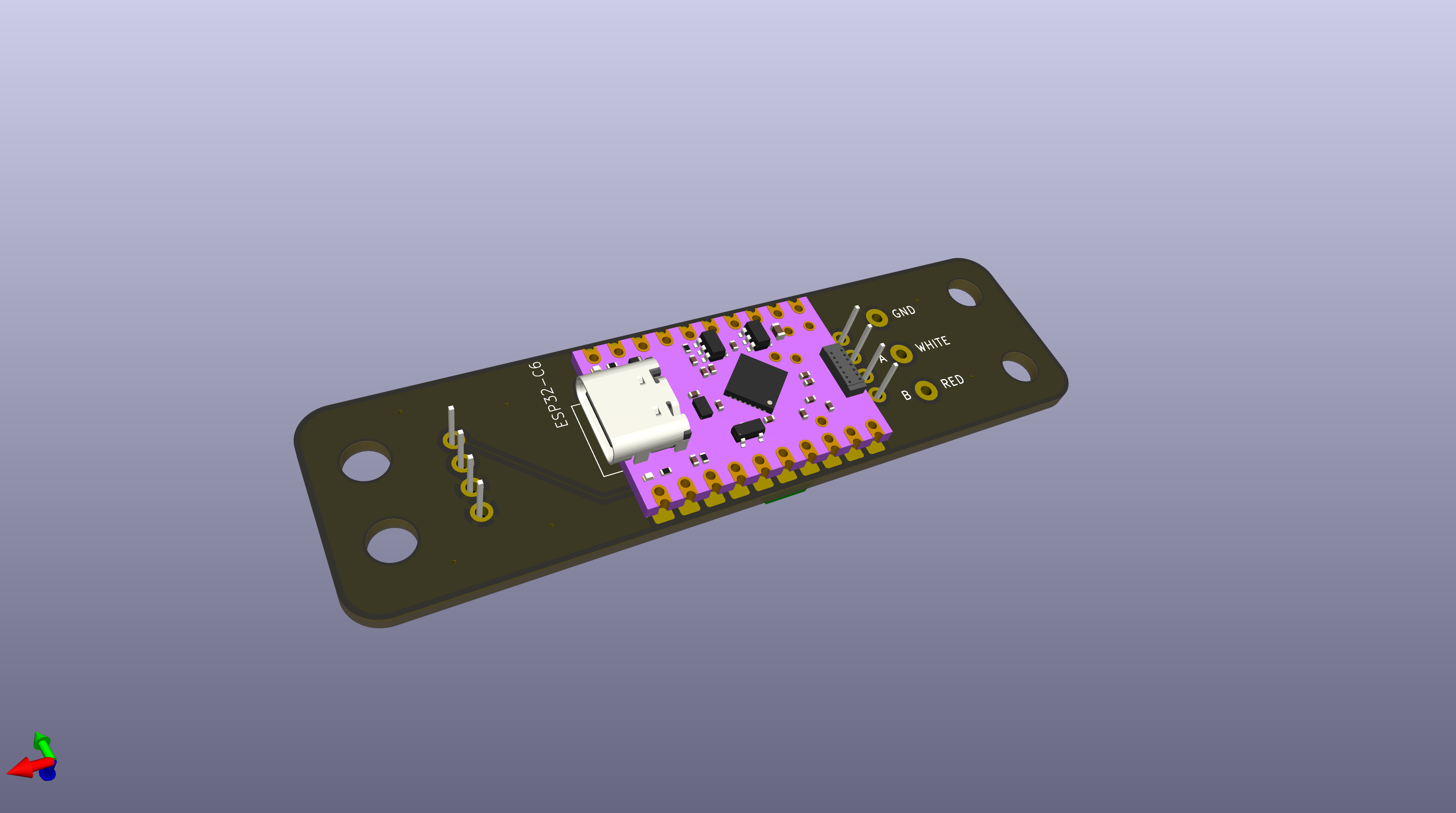
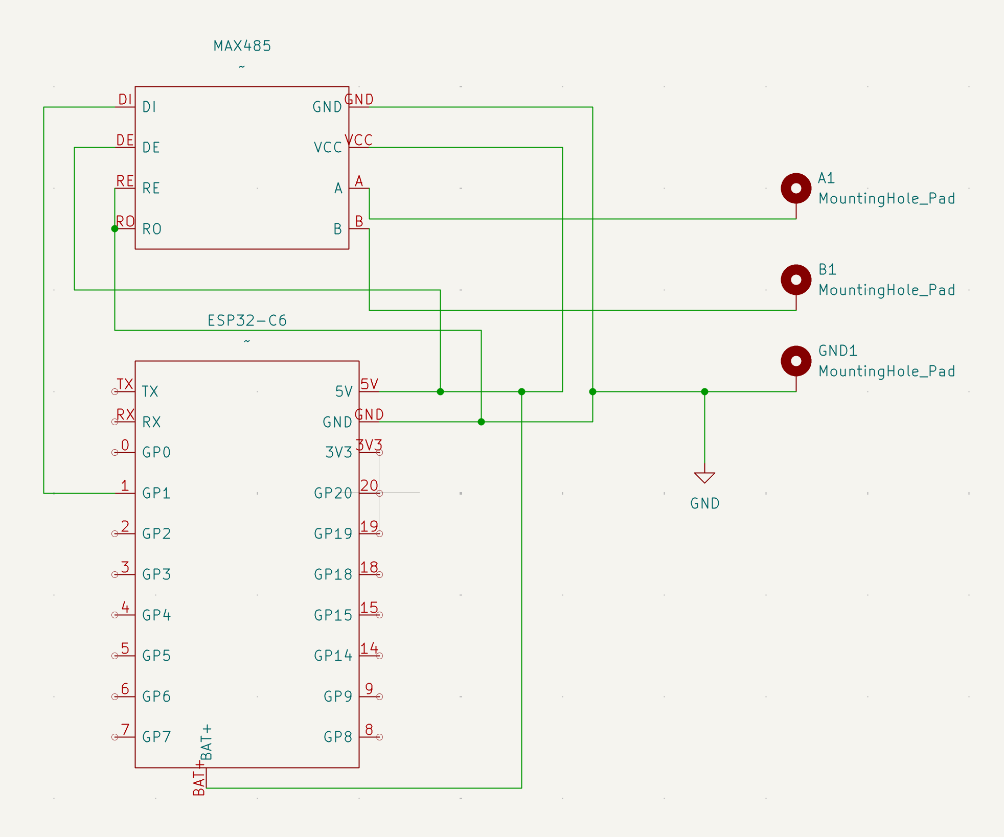
ThorDMX Bridge converts sACN lighting data over WiFi to standard DMX512 output. Open-source, easy to build, ready for the stage.

Get Started ↓
Already built your devices? Download the ThorDMX Manager app to discover, configure, and monitor your entire fleet from one place—no command line required.
ThorDMX Manager app
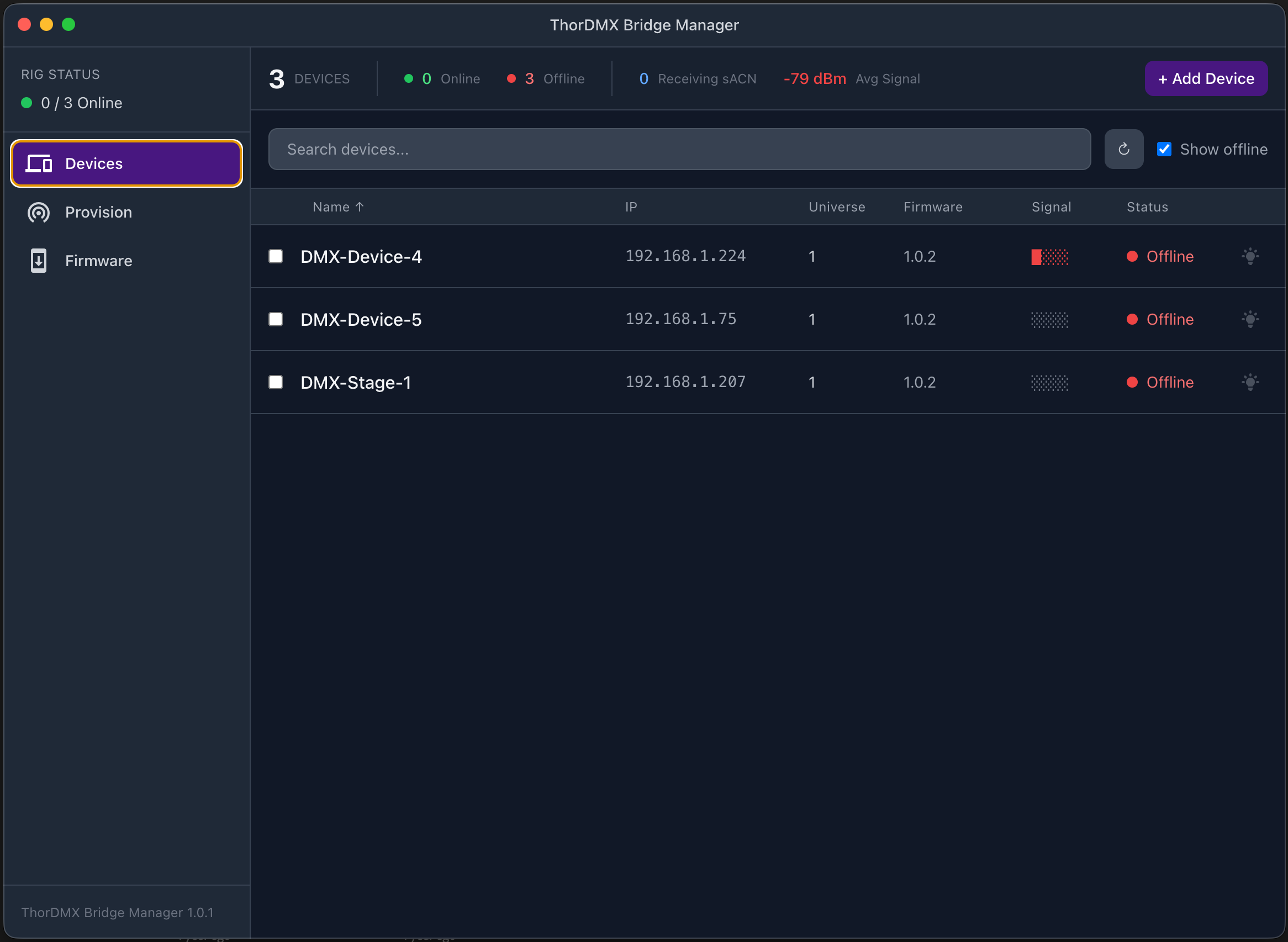
Photo: assembled ThorDMX Bridge device Add image to docs/images/hero.jpg

How It Works

Three simple steps from your lighting console to your fixtures—wirelessly.

📡

1. Send

Your lighting console sends sACN (E1.31) data over your WiFi network—just like it already does.

🛰

2. Bridge

The ThorDMX Bridge picks up the wireless signal and converts it in real time.

🎟

3. Output

Standard DMX512 comes out the XLR connector, ready for your fixtures. 40 frames per second, rock solid.

What You Need

All components are widely available and inexpensive. Total cost is roughly $10–$20 per unit.

ESP32-C6 Dev Board

The brain. WiFi-enabled microcontroller.

Any ESP32-C6 board with USB-C

MAX485 Module

Converts the signal to RS-485 for DMX output.

Pre-built breakout modules work great

5-Pin XLR Connector

Female panel-mount for DMX output.

3-pin also works

WS2812 RGB LED

Status indicator—shows connection state at a glance.

Optional but recommended

Enclosure

Any small project box. Metal preferred for shielding.

3D-printed works too

Wire & Solder

Standard hookup wire. Basic soldering required.

~30 minutes assembly time
Custom PCB available—If you prefer a cleaner build, download the Gerber files below and order PCBs from any manufacturer (JLCPCB, PCBWay, etc.).
PCB top view PCB bottom view

Build It

Basic soldering skills required. No programming knowledge needed for this step.

ThorDMX Bridge circuit schematic

Set Up the MAX485 Module

Configure the module for transmit-only mode:

  • Connect DE (Driver Enable) to VCC (always on)
  • Connect RE (Receiver Enable) to GND (disabled)

Some modules have jumpers for this—check yours.

Wire ESP32-C6 to MAX485

ESP32-C6MAX485
GPIO 0DI (Data In)
5VVCC
GNDGND

Wire MAX485 to XLR Connector

MAX485XLR PinSignal
APin 3Data+
BPin 2Data−
GNDPin 1Ground

Add the Status LED (Optional)

ESP32-C6WS2812
GPIO 8Data In
5VVCC
GNDGND

Test Your Connections

Before powering on, double-check with a multimeter:

  • No shorts between power and ground
  • MAX485 A and B are not shorted together
  • 5V reads ~5V between VCC and GND

Wiring Reference

ESP32-C6              MAX485              XLR (Female)
────────              ──────              ────────────
GPIO 0  ───────────> DI
5V      ───────────> VCC
         ───────────> DE
GND     ───────────> GND
         ───────────> RE
                      A   ─────────────> Pin 3 (Data+)
                      B   ─────────────> Pin 2 (Data-)
                      GND ─────────────> Pin 1 (Ground)

ESP32-C6              WS2812
────────              ──────
GPIO 8  ───────────> Data In
5V      ───────────> VCC
GND     ───────────> GND
Photo: completed wiring Add image to docs/images/wiring-photo.jpg

Flash the Firmware

One-time setup. After this, future updates happen wirelessly.

Install Arduino IDE

Download and install Arduino IDE 2.x (free). Works on Mac, Windows, and Linux.

Add ESP32 Board Support

In Arduino IDE:

  • Go to File → Preferences
  • In "Additional Board Manager URLs" paste:
    https://espressif.github.io/arduino-esp32/package_esp32_index.json
  • Go to Tools → Board Manager
  • Search for "esp32" and install "esp32 by Espressif Systems"

Install Required Libraries

  • ArduinoJson—Tools → Manage Libraries → search "ArduinoJson"
  • FastLED—Tools → Manage Libraries → search "FastLED"
  • sACN—Download from GitHub, then Sketch → Include Library → Add .ZIP Library

Configure Board Settings

Under Tools, set:

SettingValue
BoardESP32C6 Dev Module
Partition SchemeMinimal SPIFFS
USB CDC On BootEnabled
Upload Speed921600

Upload

Connect your ESP32-C6 via USB-C, select the correct port under Tools → Port, and click the Upload button (right arrow icon).

Wait for "Done uploading". The status LED should begin pulsing blue—that means it’s ready for setup.

Tip: After the initial flash, you can update firmware wirelessly using the Manager app—no need to plug in USB again.
Screenshot: Arduino IDE with board settings Add image to docs/images/arduino-settings.png

First-Time Setup

Once the firmware is loaded, configure your device in under a minute.

Power On the Device

Connect power via USB-C. The status LED will pulse blue—this means it’s in setup mode and broadcasting its own WiFi network.

Connect to the Device

On your phone or laptop, look for a WiFi network called DMX-Bridge-XXXX (the last 4 characters are unique to your device). Connect to it.

Open the Setup Page

A configuration page should open automatically. If it doesn’t, open a browser and go to 192.168.4.1

Enter Your Settings

  • WiFi Network—The name of your lighting network
  • WiFi Password—The network password
  • sACN Universe—Which DMX universe this device should output (1–63999)

Hit Save. The device will reboot and connect to your network. The LED turns green when connected.

Screenshot: captive portal configuration page Add image to docs/images/captive-portal.png

LED Status Reference

Pulsing BlueSetup mode (AP active)
Pulsing CyanConnecting to WiFi
Solid GreenConnected, receiving sACN
YellowConnected, no sACN data
RedError / WiFi lost
Flashing WhiteIdentify mode
PurpleFirmware updating

ThorDMX Manager App

Manage all your devices from one place. Discover, configure, monitor, and update—across your entire fleet.

ThorDMX Manager app

What It Does

Discover

Automatically finds all ThorDMX devices on your network. No IP addresses to remember.

Configure

Rename devices, assign universes, and set up WiFi credentials—individually or in bulk.

Monitor

See real-time status, signal strength, and sACN reception for every device at a glance.

Download

Bulk Provisioning

Got a rack of new devices? The Manager app can configure them all at once:

Power on all devices

Each one broadcasts its own WiFi network (DMX-Bridge-XXXX).

Open the Provision tab

The app scans for unconfigured devices automatically.

Enter your network details and naming template

For example: WiFi "ShowNet", names "Stage-1, Stage-2, Stage-3...", universes starting at 1.

Click Provision

The app connects to each device in turn, sends the config, and verifies it appears on the network.

Wireless Firmware Updates

Update any device over WiFi—no USB cable needed. The Manager app handles the upload, verification, and can even roll back if something goes wrong.

Troubleshooting

Common Issues

ProblemLikely CauseSolution
No DMX output MAX485 DE/RE not wired correctly Tie DE to VCC, RE to GND
LED stays red Can’t connect to WiFi Check SSID and password. Move closer to the router.
LED is green but fixtures don’t respond Wrong universe or swapped Data+/Data− Verify universe number matches your console. Swap XLR pins 2 & 3.
Intermittent DMX Loose connections or WiFi interference Re-solder joints. Use 5GHz network if possible. Add 120Ω terminator.
ESP32 won’t boot after wiring GPIO 0 pulled low at startup Add a 10kΩ pull-up resistor to 3.3V on GPIO 0
Status LED doesn’t light up WS2812 needs 5V Check LED is wired to 5V, not 3.3V
Can’t find device WiFi network Device already configured Factory reset: hold GPIO 9/BOOT button for 10 seconds

FAQ

Like any WiFi device, range depends on your environment. In open spaces, 30–50 meters is typical. Walls and metal structures reduce range. For large venues, use WiFi access points positioned near your devices.
Yes. Multiple ThorDMX Bridges can receive the same sACN universe simultaneously. This is useful for splitting one universe to multiple DMX runs in different locations.
Any console or software that outputs sACN (E1.31) over a network. This includes ETC Eos, ChamSys MagicQ, GrandMA, Hog, QLC+, and many others. If your console can send sACN to a network, it works with ThorDMX.
Latency is under 5 milliseconds in typical conditions—imperceptible for lighting. The device outputs DMX at a solid 40 frames per second.
Absolutely. 3-pin XLR uses the same pins (1=Ground, 2=Data−, 3=Data+). The 4th and 5th pins on 5-pin connectors are unused by DMX512.
For short cable runs or a single fixture, no. For long runs or chains of many fixtures, add a 120Ω resistor between pins 2 and 3 on the last fixture in the chain.
Hold the BOOT button on the ESP32-C6 for 10 seconds. The LED will flash red, and the device will restart in setup mode (AP mode) with default settings.